An Introduction:
Small package belt conveyors are used for thousands of applications in countless industrial markets. These conveyors move individual products through processing applications where functions such as forming, molding, machining, gluing and assembly are performed on metal or plastic product. These products then move to packaging applications where they are inserted into their individual package and sealed, wrapped, heat shrunk, or banded before being grouped and loaded into their shipping container. The use of small package belt conveyors for all of the applications presented above has several benefits.
Typically, these conveyors have end rollers between 1” and 2” in diameter. This allows smooth transfer from process to process for small and often oddly-shaped products. In addition, small package belt conveyors generally have a thin profile and have a tight belt width to overall width ratio. This provides the ability for the conveyor to fit into tight spaces, which maximizes available floor space while minimizing protrusions that may interfere with operators.
Although these conveyors are small (as their classification would imply) and their loads are generally light, they still present some of the same technical and maintenance challenges as much larger conveyors – one such challenge is belt tensioning. Forbo Siegling, a leading manufacturer of light material handling belts, notes the following relative to belt tensioning; “the contact pressure of the belt on the drive drum required to transmit effective pull is produced by elongating the belt with a tension take-up”. Without a tension take-up device, there would be no pressure on the drive drum and the conveyor belt would stop. While this concept is simple, how the tension take-up mechanism is designed to carry out this process can be quite complicated. And, if not done properly, can lead to a variety of resource-draining maintenance problems, including:
- Poor or inconsistent belt tracking
- Over-tensioning, causing poor belt life
- Over-tensioning, causing poor bearing life
- Under-tensioning, causing belt slippage
- Confusion to maintenance staff on tensioning procedures
- Mechanisms that are difficult to access or adjust
All of the issues listed previously could easily lead to conveyor belt shutdown, which often forces machine and production downtime – something that obviously needs to be avoided in today’s busy, 24/7 production facilities.
Belt Tension Methods:
There are several commercial methods for providing and adjusting conveyor belt tension. Some consist of standard components that provide the capability of designing your own conveyor. Other methods only exist in designs available as complete conveyors from conveyor manufactures. In most cases, these methods can be categorized into the following four groups:
- Jack-Screw Tension
- Rack and Pinion Tension
- Tip-up Tail Tension
- Pneumatic or Spring Tension
Let’s take a more detailed look at each of these methods, beginning with Jack-Screw Tension.
Jack-Screw Tension
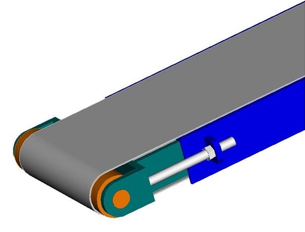
Jack-screw tension is the most common belt tensioning mechanism. How does it work? As shown in the figure below (Figure A), the tension on the belt is accomplished by turning the screw at the end of a conveyor. This pushes the bearing block towards the end of the conveyor, which adds tension to the belt. There is another, identical jack-screw located on the opposite side of the roller. The same procedure must be performed evenly for both rollers. In most conveyor installations, this tension mechanism is also used to adjust belt tracking. Jack-screw tensioning is simple to use and is commonly installed, but also presents a number of disadvantages which we’ll review in greater detail later in this paper.
Figure A: Jack-Screw Tension
Rack and Pinion Tension
Rack and pinion tension is accomplished by incorporating a rack and pinion device into the conveyor frame. An example of this mechanism is shown below (Figure B). As you’ll see, two racks are slide-ably mounted to the conveyor frame. Turning the pinion shaft then pushes on the bearing blocks to move the roller and add belt tension. Generally, the pinion runs the full width of the frame and contacts both racks, which moves the bearing blocks evenly and parallel while turning from a single point. Since the bearing blocks move together, an additional device is needed for belt tracking. This belt-tracking device may be a jack-screw or cam, which is typically mounted between the racks and the bearing block. Rack and pinion tensioning does not disturb belt tracking if/when a belt tension adjustment is necessary.
Figure B: Rack and Pinion Tension
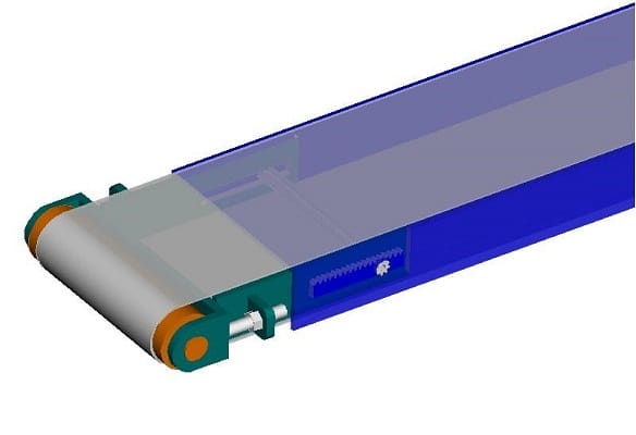
Tip-Up Tail Tension
A tip-up tail is accomplished by placing the end roller of a conveyor on a pivot mechanism. An example of this mechanism is shown below (Figure C). Using this method, the pivot device generally lifts the end roller above the conveyor frame. When placed in the lower-locked position, the total roller-to-roller length of the conveyor is longer than it is in the upper position. This extension is what provides tension to the conveyor belt. The pivot mechanism moves the entire end roller perpendicular to the conveyor frame and does not need access or adjustment from both sides of the frame. A tip-up tail mechanism will not provide finite belt tension adjustment – it can only be set to one position. Over time, as belts stretch, they will require adjustment. To accomplish this, a device such as a jack-screw will need to be added for incremental tension adjustment. This jack-screw can then also be used for belt tracking adjustment.
Figure C: Tip-Up Tail Tension
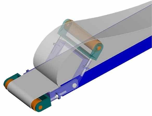
Pneumatic or Spring Tension
Pneumatic or spring tension is typically used on heavily loaded or longer conveyors. It is accomplished by the addition of at least three rollers to the underside of the conveyor. An example of this mechanism is shown below (Figure D). Belt tension is achieved by a connection of a pneumatic cylinder or a spring-loaded device to the lower tension roller. The cylinder will pull the lower roller down, which places tension on the belt. Generally, one cylinder is connected to the ends of the roller by a cross bracket. The cylinder will move the ends of the roller evenly and parallel. One benefit of this mechanism is that it automatically compensates for belt stretch. The methods covered previously in this paper have been static devices that require manual adjustment over time. Seeing as longer and higher-load conveyors have more belt stretch, this is the best method for those circumstances. Belt tracking is typically accomplished by adding a device such as a jack-screw to the snub rollers just above the tension roller.
Figure D: Pneumatic Tension
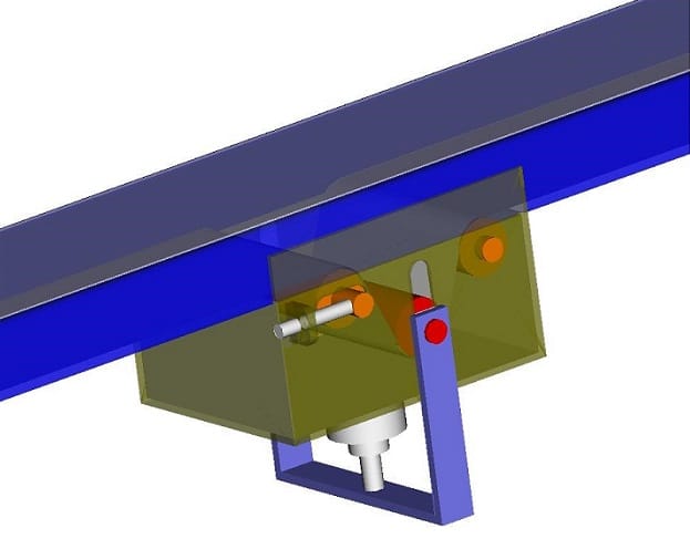
Advantages and Disadvantages of Tensioning Methods:
Now that you have a better understanding of the most commonly utilized tensioning methods, we’ll take a more detailed look at the general advantages and disadvantages of each.
Jack-Screw Tension
Advantages:
- Low cost. This method has the least amount of components and the components are simple and readily available.
- Familiarity. This is the most common method of tensioning and most maintenance crews are familiar with its operation, so it can generally be fixed quickly.
Disadvantages:
- Added maintenance time for belt tracking. Because the jack-screw is the only method of adjustment, it must be used for both tensioning and tracking. Once a conveyor belt requires re-tensioning, the jack screws will be adjusted and the tracking settings will be disturbed. Therefore, a tracking adjustment must be performed even though it wasn’t required. This causes much higher maintenance times as tracking adjustment can take substantially longer than simple tensioning alone.
- High risk of over tensioning. In most cases, the jack-screw adjustment device is a simple threaded bolt. Threaded bolts are designed to apply extreme force to clamp or hold devices. Belt tension adjustments made with jack-screws are done manually. And, with the shallow pitch angle of the jack-screw thread, there is very little “feedback” to the operator making the adjustment. They are often unaware of the extreme forces they are placing on the belt and the bearings. Unfortunately, in time, this over tensioning will result in reduced bearing and belt life.
- Difficult to access for maintenance. In many conveyor designs, the jack-screw is located at the end of the conveyor roller along the side of the conveyor frame. Unfortunately, in most applications, the end of the conveyor is placed up against another conveyor roller or piece of equipment, making it nearly impossible to access the end of the jack-screw for adjustment. Therefore, to make adjustments, the conveyor must be removed from it mounts, adjusted and then returned. This dramatically increases maintenance times.
- Adds width to the conveyor. If not located on the end of the conveyor tail, the jack-screw must then be located behind the conveyor bearing block, which pushes the bearing block forward (see Figure A). This method adds considerable width to the overall conveyor, making it much more difficult to place the conveyor into tight applications. It also protrudes beyond the conveyor side frame, which creates a potential safety risk for operators.
- Requires periodic re-tensioning. This mechanism does not compensate for the belt stretch that will occur over time due to wear or heavy loads. If belt slip occurs, the jack-screw will need to be re-tightened and re-tracked to tension the belt.
Rack and Pinion Tension
Advantages:
- Does not affect belt tracking. Rack and pinion mechanisms push evenly on the bearing blocks from a single point. Moving the bearing blocks together ensures that the tracking adjustment completed previously does not get disturbed by the need to re-tension. This greatly shortens maintenance times.
- Easy access for maintenance adjustment. Maintenance adjustment on a rack and pinion system is done from the side of the conveyor frame. Generally, this area is more open than the end. In addition, the pinion can be accessed from either side of the frame. Therefore, if one side is blocked by an accessory, the other side may be open.
- Low risk of over-tensioning. In a rack and pinion mechanism, the amount of tension placed into the conveyor belt is directly related to the manual torque placed on the pinion gear. The mechanical advantage of this pinion gear is much less than a jack-screw. The pinion can be sized so that when it reaches the desired belt tension, it becomes difficult to turn. This minimizes the desire to over-tension the belt, lengthening conveyor belt and bearing life.
- Compact design. Only the end of the pinion needs to be accessed by maintenance in a rack and pinion design. As a result, the remainder of the mechanism can be built inside the conveyor frame. This ensures the frame is narrow and does not protrude much past the belt width, allowing the conveyor to be placed into tight spaces while eliminating operator bump points.
Disadvantages:
- Requires an accurate frame. Since the premise for this mechanism is to move the two bearing blocks evenly, it is critical for it to be installed accurately and parallel to the roller. Custom conveyors generally do not use this method for that reason. However, standard conveyors that use quality engineering and consistent manufacturing methods are able to accomplish the accuracy needed.
- Requires periodic re-tensioning. This mechanism does not compensate for the belt stretch that will happen over time due to wear or heavy loads. If belt slip occurs, the rack and pinion will need to be re-tightened to tension the belt.
Tip-Up Tail Tension
Advantages:
- Quick access for cleaning. Tip-up tail tension mechanisms are most often utilized on conveyors used in food applications. For these applications, it is important to have fast and tool-less access to the inside of the conveyor for cleaning. Tip-up tails provide this function.
- Does not affect belt tracking. Tip-up mechanisms swing the bearing blocks evenly into position from a single point. Moving the bearing blocks together ensures that the tracking adjustment that has been previously set does not get disturbed by the need to re-tension.
Disadvantages:
- Requires an accurate frame. Since the premise for this mechanism is to move the two bearing blocks evenly, it is required that it is installed accurately and parallel to the roller.
- Only sets initial tension. A tip-up tail tension system is a single-position system. The pivot arm rotates the roller into one position only. Therefore, this tension system can only set initial tension and cannot compensate for belt stretch over time. To accommodate this, an additional device such as a jack-screw must be added to the mechanism.
- Operator safety hazards. The use of a tip-up tail mechanism creates two potential operator hazards. The first is the potential to lift the tip-up tail into the upper position while the conveyor is running. If this is done, the operator has access to driven rollers inside the conveyor frame. CE Safety Standards dictate that access to equipment shall only be done using a tool. If the tail is manually activated, it may violate CE and OSHA safety standards. Manually activated tip-up tails are preferred in Food conveyor applications. In these applications, the need for sanitation outweighs the potential safety risks. The second safety hazard with tip-up tail mechanisms is the potential pinch point created from lowering the tail back down into its tensioned position. The scissors action created from the pivot frame to the conveyor frame creates a danger point. If not properly designed or guarded, injury could occur.
Pneumatic or Spring Tension
Advantages:
1. Automatically tensions the belt. With the addition of a pneumatic cylinder or spring loaded device, this tension mechanism maintains constant tension on the conveyor belt. This is especially important on longer or heavily-loaded conveyors. Re-tension maintenance is not required until the mechanism runs out of travel.
Disadvantages:
1. Costly. The addition of the three rollers and the tension mechanism adds significantly to the cost of the conveyor.
2. Longer belt replacement time. In this tension method, the return conveyor belt is interwoven through the three rollers. When belt replacement is required, removal of the upper two rollers is also necessary. Depending on the design of the mechanism, this can add significantly to the maintenance time to replace a worn out belt. To increase maintenance efficiency, a system with a quick-release feature should be utilized, which provides easy access to the top rollers.
3. Belt surface contamination. With the three roller mechanism, the top two rollers contact the top running surface of the belt. These rollers can pick up debris and imbed it into the belt surface. In some applications this may not be an issue, but in food or food packaging applications, this should be avoided.
Conclusion:
So, which method of belt tensioning is best? Of course, the correct answer depends on the specific application at hand. But, generally speaking, in a situation where a one-off custom conveyor is being implemented by non-conveyor people – the jack-screw method would most likely be sufficient. It has readily available components to aide in the design and it’s also simple and inexpensive.
However, when a company is purchasing a conveyor from a conveyor manufacturer, they should expect more utility for their money and higher-quality technology. A technology that decreases maintenance times, while prolonging the conveyor’s life and improving its overall function. The technology that most regularly delivers these benefits is the Rack and Pinion method.
For more details about Rack and Pinion tensioning, or any of the other methods presented in this paper, please call Dorner Mfg. Corp. at 1-800-397-8664 or visit Dorner.com.


